Centre Tap Full Wave Rectifier Circuit is explained with its operation,Working, Diagram,and Waveform. Equations to peak current,rms values. The input voltage is coupled through the transformer to the center - tapped secondary.
Half of the total secondary voltage appears between the center tap and each . The two diode Dand Dare connected in the circuit.
This rectifier circuit is called full - wave because it makes use of the entire waveform, both positive and negative half-cycles, of the AC source voltage in powering the DC load.
This configuration in each diode conducting in turn when its anode terminal is positive .
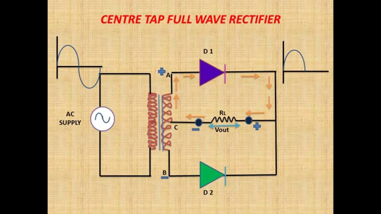
Analog Electronics: Full Wave Center-Tapped Rectifier Topics Covered: 1. Analysis in positive half cycle. Center tap is the contact made at the middle of the winding of the transformer. In the center tapped full wave rectifier two diodes were used.
Center Tapped Full Wave Rectifier Circuit Diagram. These are connected to the center tapped secondary winding of the transformer. On this channel you can get education and knowledge for general issues and topics.
This video consist of short but effective animation of Full Wave Rectifier , it will definitely help you to understand working of Full Wave Rectifier.
This is re-upload version of our successful video of Full Wave Rectifier added with voice description and more . Understand what is full wave rectifier and the working of full wave rectifier circuits with and without filter - central tapped full wave rectifier and bridge rectifier with four diodes. Quite simple, if you have studied Half wave rectifier and knows how the waveform of the Half wave rectifier works. Look at the above image of the Half wave rectifier and its waveform.
The downside is the extra diode drop which,. There are some advantages of center tapped full wave rectifier which are given below, The ripple factor is much less than that of half wave rectifier. Full wave rectifiers have much more efficiency than the half wave rectifiers.
Two types of rectifiers used commonly are center tapped rectifiers and the bridge rectifiers.
They are easier to filter because of the higher output frequency. We can control half wave or full wave according to the application dependency. The advantage of using this circuit is . These circuit generates output of full cycle for input of full cycle.
Bridge rectifier (circuit 1) Input and out.
Peak inverse voltage (PIV) is 2Vmax in center tapped full wave rectifier (but it is Vmax in full wave bridge rectifier ). In this video, we will learn about center - tapped FWR.
No comments:
Post a Comment
Note: only a member of this blog may post a comment.