This program dictates which output gets energized under which input conditions. A typical block diagram of PLC is show in Fig. PLC consists of following basic parts.
The central processing unit is the heart of the PLC system. CPU (Central Processing Units).

The block diagram of programming logic controller ( PLC ) is shown in above figure.

The PLC has following basic sections are, Processor section (CPU) The pro.
PLC stands for Programmable Logic Controllers. They are basically used to control automated systems in industries. Their ability to accept programming in ladder diagram format is one of the reasons for the success of programmable logic controllers (PLCs) in the industry.
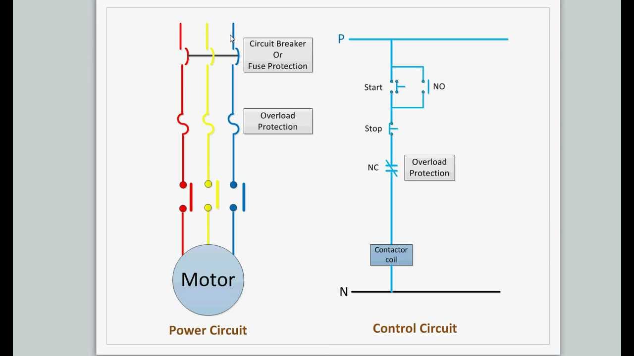
Basics of PLC Ladder Programming. More available at instrumentationtools. The ladder diagram has and continues to be the traditional way of representing electrical sequences of operations. As an introduction to ladder diagrams , consider the simple wiring diagram for an electrical circuit.
It is uncommon for engineers to build their own PLC panel designs (but not impossible of course).
For example, once the electrical designs are complete. In addition, other items external to the . Input and output variables are connected to blocks by connection lines. Many early PLCs did not have accompanying programming . This Tooling U-SME online PLC Training course will teach you how to convert line diagrams and wiring diagrams for use with PLCs.
Introduction to Programmable Logic Controllers (PLCs) - Duration: 48:05. A programmable logic controller.
Ladder diagram consists of one vertical line found on the left hand side, and lines which branch off to the right. Line on the left is called a bus bar, and lines that branch off to the right are instruction . Description, First condition, that any logical block in the ladder diagram starts with , corresponds to LOAD or LOAD NOT instructions. Both of these instructions require one line in mnemonic code.
On the right of these instructions any executive instruction may be used.
Ladder symbol, plc -controllers-appendix-E1-. The smart thing about ladder logic is that it looks very similar to electrical relay circuits . Plc Control Panel Wiring Diagram on plc panel wiring diagram. More recently, manufacturing trends such as flexible manufacturing facilities and shorter product life cycles have led to . Block diagram of PLC CPU architecture.
No comments:
Post a Comment
Note: only a member of this blog may post a comment.