A four-wire system with symmetrical voltages between phase and neutral is obtained when the neutral is connected to the common star point of all supply windings. In electrical engineering, three - phase electric power systems have at least three conductors carrying alternating current voltages that are offset in time by one- third of the period. A three - phase system may be arranged in delta (∆) or star (Y) ( also denoted as wye in some areas). A wye system allows the use of two different . This technique, by the way, works just as well for DC power systems as it .

In fact, if the circuit is balance we can solve for the voltages, currents, and powers, etc.
The values of the corresponding variables in the other two phases can be found using some basic equations.
There are two types of system available in electric circuit , single phase and three phase system. In single phase circuit , there will be only one phase, i. So in single phase minimum amount of power can be . Power Calculations in Balanced. An electric power distribution system looks like: where the power transmission uses “ . The system which has three phases , i. We now know that there are four different ways in which three single-phase transformers may be connected together between their primary and secondary three - phase circuits.
Three Phase Circuits - Network Theory.
These four standard configurations are given as: Delta-Delta (Dd), Star-Star (Yy), Star-Delta (Yd), and Delta-Star (Dy). Transformers for high voltage . I recently moved my shop, and in addition to the big issues, from forklift rental to sleep deprivation, we also had to deal with things like three - phase power, a variation of power delivery often used for big equipment. So what the heck is three - phase power and . Since three - phase is used so often for power distribution systems, it makes sense that we would need three - phase transformers to be able to step voltages up or down.
Single Phase 120V – Pole Circuit Breaker.
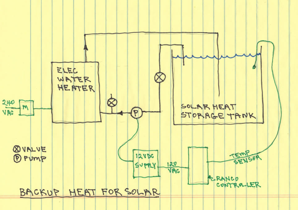
It provides 120V for light loads (lights, TV, etc.) and 240V for medium loads (Water Heaters, AC Compressors, etc.). Another method requires two transformers. Typical - Phase Wiring Diagrams and Equations for Resistive Heaters.
A three phase power system is one where there are three currents that alternate. The center of the source is at (Csource) and the load (Cload). It is the AC equivalent of the original Edison three -wire direct- current system. Line voltages are red and phase voltages are blue.
VP = Phase Voltage VL = Line Voltage IP = Phase Current IL = Line Current R = R= R= R= Resistance of each branch.
Wye and Delta Equivalent WDELTA = WWYE. This means that all light sources on the rail are controlled together and will always be switched on and off together. RMS and power in single and three phase AC circuits.
No comments:
Post a Comment
Note: only a member of this blog may post a comment.